About Us
“Providing Solution to Contaminants”
Innovation, dynamism, ethics and teamwork are the fundamental virtues that make up the bed rock on which HG Solution builds on.
Established in 2005 as a company that specifically provides solutions to mercury contaminants
produced along upstream and downstream oil and gas processing facilities, Hg Solution today is recognized
globally as the preferred service provider for managing not only mercury but a variety of contaminants that are
produced in the oil and gas and petrochemical industry.
VISION
To be recognized as a global leader in the field of mercury management and a corporate entity synonymous with quality services.
MISSION
At Hg Solution, we constantly pioneer and develop new techniques and technologies to manage and mitigate mercury contaminants either independently or in collaboration with other recognized research institutions. We constantly strive to deliver quality service, every time by understanding your organizational needs to ensure a contaminant free working environment.
Consultancy for Mercury & Wastes Management Planning
 Mercury is an element that is naturally present in oil and gas reservoirs worldwide. Due to its unique properties, mercury introduces various challenges in the oil and gas industry due to its degrading effects on metals.
Mercury is also a neurotoxin that is harmful to humans and the environment.
Keeping at heart the “Cradle to Grave” concept, we provide consultation for a holistic solution that includes procedure write ups, feasibility studies, chemical health risk assessments, training and wastes management.


Services
Mercury Assessment and Baseline Study
A structured method to detect the presence of mercury or its compounds within the process lines of a certain facility. Using this method, the distribution and concentration of mercury can accurately be projected without the need to interfere with day to day production activities.
How it’s done?
We determine critical representative sampling points for a wide range of facilities. This includes offshore installation platforms down to downstream petrochemical plants. We then perform an analysis to compute the total mercury concentration present strictly adhering to internationally recognized standards and protocols. Utilizing state of the art mercury analysis equipment, we deliver highly accurate results in all our undertaking tasks. By doing so, potential mercury accumulation and distribution patterns in oil and gas processing facilities as well as other relevant industries can be reliably projected.
 Why the Study?
 The ability to accurately project its accumulation and distribution pattern will certainly assist you to judiciously arrange the necessary HSE preparation to protect your workers from the hazards of mercury. Pro-active measures can also be taken to protect all sensitive equipment that may be damaged due to amalgamation such as aluminum heat exchangers aka Cold Box. Besides that, the effectiveness of any adsorbent or catalyst used in mercury removal units (MRU) can also be determined with this study.
HAZMAT Handling of Mercury during Maintenance & Turnaround


At HG SOLUTION we provide a specialized team that will monitor the level of exposure towards mercury and enforce work procedures that will mitigate the impact of mercury towards personnel and the environment.
The main objective is to ensure a safe working environment and to minimize to as low as reasonably possible any cross contamination when dealing with mercury or its compounds.
Mercury & TENORM Laboratory Analysis


MS ISO/IEC 17025
TESTING SAMM NO. 441
| FIELD OF TESTING: CHEMICAL | ||
| Material/ Product tested | Types of test/ Properties measured/ Range of measurement | Standard test method/ Equipment/Technique |
|
Petroleum & Petroleum Products
1. Liquid Hydrocarbon (Light & Heavy) 2. Gas 3. Liquid & Solid |
Total Mercury Total Mercury Total Mercury |
UOP 938-00 (1) ASTM D5954-98 (2) In-house Method IH-938-7473-09 |
Utilizing state of the art equipment and highly skilled personnel, our ISO/IEC 17025 certified laboratory is specialized in conducting Mercury Analysis and TENORM Analysis in various samples.
Total mercury can be measured in samples such as crude, condensate, water, gas and sludge whilst TENORM gross alpha & beta activity can be carried out for environmental samples (soil, flora, fauna, sediment, etc), mineral water samples, air born particles and smear test samples.
The analysis of total mercury & TENORM activity adheres to strict protocols of quality and internationally recognized standards.
Mercury Treatment of Contaminated Tools & Equipment
 Mercury is known for its ability to amalgamate and form a liquid metal solution with precious metals.
It will react with alloying constituents of contaminated metals and remain within the metal structure
itself. Sensitizing of the intermetallic compounds during heat application can somewhat affect the structural
integrity of the based metals. If the alloying elements are not susceptible for sensitization, amalgamated mercury
will tend to remain within the grain boundaries of the contacted metal itself thus, proper decontamination is required to ensure mercury exposure is eliminated.
Mercury is known for its ability to amalgamate and form a liquid metal solution with precious metals.
It will react with alloying constituents of contaminated metals and remain within the metal structure
itself. Sensitizing of the intermetallic compounds during heat application can somewhat affect the structural
integrity of the based metals. If the alloying elements are not susceptible for sensitization, amalgamated mercury
will tend to remain within the grain boundaries of the contacted metal itself thus, proper decontamination is required to ensure mercury exposure is eliminated.
We have developed a system to decontaminate tools or equipment. The system is a combination of the application of specialized chemicals and the application of uniformed heat. This will result in the release of mercury trapped in the grain boundary of materials. Once completed, a certificate of fitness is issued for the treated items.
Materials treatment process will be monitored strictly adhere to the Department of Environment (DOE) requirement and certificate of fitness will be produced for each treated items. The treated item can therefore be reused again, reconditioned or resold for a value.


Chemical / Noise Exposure Monitoring & Other Hygiene Activities


Under the Occupational Safety and Health (Use and Standard of Exposure of Chemicals Hazardous to Health) Regulations 2000, where an assessment of risk to health indicates that monitoring of exposure is required or it is requisite for ensuring the maintenance of adequate control of the exposure of employees to chemicals hazardous to health, the employers shall ensure that the exposures of chemicals hazardous to health is monitored in accordance with an approved method of monitoring and analysis.
Personal Noise Exposure Monitoring is a method used to determine the noise level in a workplace to have healthy working environment that comply with Factories and Machinery (Noise Exposure) Regulations, 1989. The Management will use the monitoring as their baseline data for further action where necessary.
PEM for chemical and noise must be conducted by Hygiene Technician and Noise Competent person respectively, whom registered with DOSH. HGS is one of the service providers which offers PEM for noise and chemical hazardous to health listed in schedule I or II of the Occupational Safety and Health (Use and Standard of Exposure of Chemicals Hazardous to Health) Regulations 2000 such as Benzene, Toluene, Xylene, Mercury, etc.
Awareness Training for Mercury, TENORM & other Toxic Substances

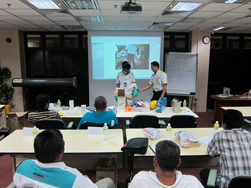

As a company specialized in mercury and other contaminants, HG Solution provides mercury awareness training and comprehensive training for “Mercury HAZMAT Teams”.
The training provided covers Basic Mercury Awareness Training for any personnel or crew involved in operation, turnaround and the daily maintenance of process equipment that has been identified to have possible mercury accumulation. Comprehensive training with hands-on practical exercise for mercury Hazmat Handling is provided for the formation of an in-house Mercury Hazmat Team to tackle day to day task.
Other Training Programs
HG Solution Sdn Bhd also caters to other areas of training that are related to hazardous waste. Such programs include:
• Scheduled Wastes Management
• Technologically Enhanced Naturally Occurring
• Radio Active Materials (TENORM)
• H2S (Hydrogen Sulphide) Awareness
TENORM Inspection and Monitoring Services

 Naturally Occurring Radioactive Materials (NORM) encountered in oil and gas and mining operations
originate in subsurface formations, which may contain radioactive materials such as uranium,
thorium, radium 226 and radium 228. The exploration, development and production activities will
enhance NORM which will eventually be brought to the surface.
Naturally Occurring Radioactive Materials (NORM) encountered in oil and gas and mining operations
originate in subsurface formations, which may contain radioactive materials such as uranium,
thorium, radium 226 and radium 228. The exploration, development and production activities will
enhance NORM which will eventually be brought to the surface.
We offer Low Specific Activity (LSA) / Technologically Enhanced Naturally Occurring Radioactive Material (TENORM) Routine or Specific Monitoring and radioactive source Leak Test Services. It involves the monitoring, surveillance and laboratory analysis of:-
• External radiation level
• Surface contamination level
• Airborne radionuclide
• Leak Test
• Radon / Thoron progeny levels
• Radioactivity analysis of mineral by-products sludge, scale, soil, liquids and flora/fauna.
Mercury Related Equipment & Chemical Supply

Distributed by
HGS SERVICES SDN BHD
Wholly owned subsidiary by
HG SOLUTION SDN BHD
Mercury Spill Kit
The kit contains basic personal safety wear, clean-up equipment and Mercury Magnet amalgamation powder. Designed for a quick and effective response to mercury spills, including switches, thermometers, and fluorescent bulbs. The Mercury Magnet Spill Control kits include everything you need to clean up and recycle mercury spills quickly and safely.
Mercury Magnet is effectively used in the following work areas:
• Oil & Gas offshore/onshore facilities
• Chemical laboratories
• Hospitals
• University laboratories
• Plants where neon signs, batteries, fluorescent and high intensity discharge lamps and mercury type instruments are manufactured and repaired
• Dental offices and laboratories
Mercury Vapor Suppressant Chemical


HG Solution Sdn Bhd is the patent owner of HGS 308. The chemical is mainly used during maintenance and turnaround activities to suppress mercury vapors in order to minimize the risk of inhalation by workers.
Chemical Protective Suit Covtech
Presenting CovTechTM: A superior and premium, innocatively-designed, disposable protective garment. Lightweight, breathable, durabel and certified resistant to limited chemical splash, radioactive particulates, viral and blood-borne pathogens, with antistatic properties.
Respiratory PPE & Others
We provide a wide array of other PPE form various reputable brands such as respirators from 3M, chemical suits from Dupont, and nitrile gloves from Ansell. Contact us for a complete list of products.
Distributed by
HGS SERVICES SDN BHD
Wholly owned subsidiary by
HG SOLUTION SDN BHD
Computational fluid dynamics (CFD)
Ongoing research yields software that improves the accuracy and speed of complex simulation scenarios such as transonic or turbulent flows. Initial validation of such software is typically performed using experimental apparatus such as wind tunnels. In addition, previously performed analytical or empirical analysis of a particular problem can be used for comparison. A final validation is often performed using full-scale testing, such as flight tests.
CFD is particularly useful for oil and gas applications to improve design or to trouble shoot inefficient equipment or systems such as valves, pumps, cyclones, pressure vessels, etc.
It can also be applied to a wide range of research and engineering problems in other fields of study and industries, including aerodynamics and aerospace analysis, weather simulation, natural science and environmental engineering, industrial system design and analysis, biological engineering, fluid flows and heat transfer, and engine and combustion analysis.
VALVES
|
|
PUMPS |
|
|
|
CYCLONE SEPARATORS
|
|
HEAT EXCHANGERS
|
|
|
|
PIPELINE FLOW |
|
EROSION ANALYSIS
|
|
|
|
THERMAL ANALYSIS |
|
MULTIPHASE FLOW
|
|
|
|


Training Schedule
For enquiries and bookings, email us at training@hgsolution.com.my, whatsapp us at +6019-6983217, or connect with us via facebook.
| CLASSROOM COURSES AT HG SOLUTION, TERENGGANU (EAST COAST): | ||||
|---|---|---|---|---|
| Code | Course Title | Recognition | Dates | Duration (day) |
| RSH 101E |
Kesedaran Keselamatan Sinaran Radiation Safety Awareness Download Training Brochure & Booking Form |
CEP (AELB) |
|
1 |
| RSH 300E |
Perlindungan Sinaran untuk Pegawai Radiation Protection for Officer Download Training Brochure & Booking Form |
CEP (AELB) |
|
9 |
| RSH 301E |
Prosedur Keselamatan & Kecemasan Sinaran Radiation Safety & Emergency Procedure Download Training Brochure & Booking Form |
CEP (AELB) |
|
2 |
| MXR 201E | Kursus Latihan Sinar-X untuk Pengamal Perubatan Am Training Course on X-ray for General Practitioner Download Training Brochure & Booking Form |
CEP (AELB) |
|
6 |
| NET 110E | Arus Pusar Tahap 1 (Peringkat Asas) Eddy Current Level I (Basic Grade) Download Training Brochure & Booking Form |
CEP (AELB) |
|
6 |
| NRT 111E | Radiografi Industri Tahap 1 (Peringkat Asas) Industrial Radiography Level 1 (Basic Grade) Download Training Brochure & Booking Form |
CEP (AELB) |
|
12 |
| NRT 211E | Radiografi Industri Tahap 2 (Peringkat Pertengahan) Industrial Radiography Level 2 (Intermediate Grade) Download Training Brochure & Booking Form |
CEP (AELB) |
|
15 |
| ESH 110E | Asas Keselamatan Sinaran Tidak Mengion Basic Non-Ionising Radiation Safety Download Training Brochure & Booking Form |
CEP (AELB) |
|
3 |
| ESH 112E | Pemantauan Radiasi Radiofrekuensi (RF) untuk struktur Telekomunikasi Surveillance of Radio Frequency (RF) Radiation for Telecommunication Structure Download Training Brochure & Booking Form |
CEP (AELB) |
|
3 |
| ESH 126E | Kesedaran Keselamatan Laser Laser Safety Awareness Download Training Brochure & Booking Form |
CEP (AELB) |
|
1 |
| ESH 300E | Keselamatan Laser untuk Pegawai Laser Safety for Officer Download Training Brochure & Booking Form |
CEP (AELB) |
|
5 |
| ONLINE COURSES VIA ZOOM: | ||||
| Code | Course Title | Recognition | Dates | Duration (day) |
| RSH 101E | Kesedaran Keselamatan Sinaran Radiation Safety Awareness Download Training Brochure & Booking Form |
CEP (AELB) |
|
2 (7 Jam) |
| RSH 300E | Perlindungan Sinaran untuk Pegawai Radiation Protection for Officer Download Training Brochure & Booking Form |
CEP (AELB) |
|
TBA |
| RSH 301E | Perlindungan Sinaran untuk Pegawai Radiation Protection for Officer Download Training Brochure & Booking Form Download Training Brochure & Booking Form |
CEP (AELB) |
|
TBA |
| MXR 201E | Kursus Latihan Sinar-X untuk Pengamal Perubatan Am Training Course on X-ray for General Practitioner Download Training Brochure & Booking Form |
CPD |
|
6 (40 hrs) |
| NET 110E | Arus Pusar Tahap 1 (Peringkat Asas) Eddy Current Level I (Basic Grade) Download Training Brochure & Booking Form |
SKM 1 |
|
TBA |
| NRT 111E | Radiografi Industri Tahap 1 (Peringkat Asas) Industrial Radiography Level 1 (Basic Grade) Download Training Brochure & Booking Form |
CEP (AELB) |
|
TBA |
| NRT 211E | Radiografi Industri Tahap 2 (Peringkat Pertengahan) Industrial Radiography Level 2 (Intermediate Grade) Download Training Brochure & Booking Form |
CEP (AELB) 20CCD SKM II |
|
TBA |
| ESH 110E | Asas Keselamatan Sinaran Tidak Mengion Basic Non-Ionising Radiation Safety Download Training Brochure & Booking Form |
CEP (AELB) |
|
TBA |
| ESH 112E | Pemantauan Radiasi Radiofrekuensi (RF) untuk struktur Telekomunikasi 'Surveillance of Radio Frequency (RF) Radiation for Telecommunication Structure Download Training Brochure & Booking Form |
CEP (AELB) |
|
3 |
| ESH 126E | Kesedaran Keselamatan Laser Laser Safety Awareness Download Training Brochure & Booking Form |
CPD |
|
1 |
| ESH 300E | Keselamatan Laser untuk Pegawai Laser Safety for Officer Download Training Brochure & Booking Form |
CPD |
|
5 |
Licences & Quality
Petroliam National Berhad
(Petronas)
Reg.No:L-705531-T

Licence No: LPTA/A/1832
MS ISO/IEC 17025
TESTING SAMM NO.441
Clientele
we at Hg Solution Sdn Bhd would like to extend our deepest gratitude and appreciation for your continunous support in our products and services over the year. Your confidence in our organization will forever be a driving force that propels us towards greater achievements. we strive to serve you better.

| OTHER CLIENTS | |
| ANALYTIC PIPE ASIA SDN BHD | PETROFAC LIMITED |
| BAYU PURNAMA SDN BHD | PETRONAS CARIGALI SDN BHD |
| CCM FERTILIZERS SDN BHD | PETRONAS CHEMICALS AMMONIA SDN BHD |
| CETCO OILFIELD SERVICES (M) SDN BHD | PETRONAS CHEMICALS DERIVATIVES SDN BHD |
| COMPLETE OIL FIELD STIMULATION AND SERVICES SDN BHD | PETRONAS CHEMICALS ETHYLENE SDN BHD |
| DAYANG ENTERPRISE SDN BHD | PETRONAS CHEMICALS MTBE SDN BHD |
| EPOM SERVICES SDN BHD | PETRONAS GAS BERHAD |
| ETHYLENE MALAYSIA SDN BHD | PETRONAS RESEARCH SDN BHD |
| FPSO VENTURES SDN BHD | PLC INTERNATIONAL SDN BHD |
| GEO WELL SDN BHD | QUARTERBACK SEVICES SDN BHD |
| HIGHBASE STRATEGIC SDN BHD | SAPURAKENCANA CONSTRUCTOR MERMAID NUSANTARA |
| HYPERWAVE SYSTEM ENGINEERING | SAPURA EXPLORATION PRODUCTION (SARAWAK INC) |
| INTISARI MULIA ENGINEERING SDN BHD | SHAPADU ENERGY ENGINEERING SDN BHD |
| M3NERGY FPSO PERINTIS SDN BHD | TRACTORS PETROLEUM SERVICES SDN BHD |
| M3NERGY JDA SDN BHD | TRENERGY FPSO SDN BHD |
| MAMPAN JITU (M) SDN BHD | UNIVERSITY TEKNOLOGI PETRONAS |
| NEWFIELD PENINSULA MALAYSIA INC. | UPSTREAM DOWNSTREAM PROCESS SERVICES SDN BHD |
| OCEAN CARE SDN BHD | VENATOR ASIA SDN BHD |
| PETRA RESOURCES SDN BHD | |
Video & Literature


Literature From 2005 - Present
3-5 December 2008 - Kuala Lumpur, Malaysia
Abstract Submission
Mercury in SE Asia Produced Fluids - Holistic Approach to Managing Offshore Impacts
S. Mark Wilhelm, President, Mercury Technology Services (smw@hgtech.com) Ahmad Afdzal Md Isa, Executive Director, HG Solution Sdn Bhd (afdzal@hgsolution.com.my) Shaharuddin Safri, Managing Director, HG Solution Sdn Bhd (shah@hgsolution.com.my)
Category: OVER-ARCHING INDUSTRY ISSUES
ABSTRACT
Mercury is a naturally occurring constituent of oil and gas produced in SE Asia. In fact, average mercury concentrations in SE Asia produced fluids are the highest in the world. Actions to avoid consequences to oil and gas offshore operations have been gained through experience and include implementing special health and safety precautions for workers, selecting materials and designing equipment to avoid degradation, developing procedures to decontaminate equipment, monitoring discharges for environmental protection and mercury removal to ensure product quality. Often actions and policies come from reaction to acute problems rather than from advance planning. An integrated approach to mercury management can minimize negative impacts and reduce operating cost. Consideration should be given to the consequence of mercury from the initial stages of field development. A holistic approach to managing potential impacts involves several steps:
-Forecasting reservoir mercury concentrations from geology
-Measuring mercury in drill stem tests
-Design of facilities to ensure integrity
-Confirming amounts in early production
-Modeling of mercury species to predict partition and deposition
-Analytical mapping to confirm predictions
-Training and education of workers
-Monitoring mercury in air in work environments
-Biological monitoring for selected work activities
-Advance planning for turn-around to allow decontamination
-Development of mercury waste plan
-Provision of clear company policies and action levels
-Planning for decommissioning early on
Because the necessary steps cross many company organizational boundaries, an integrated top-down and bottom-up plan should be adopted with worker protection and process integrity paramount. Mercury in process fluids can be handled routinely with little negative consequences if a holistic and integrated plan is adopted.
Removal of Mercury and Arsenic from Produced Water
Darrell L. Gallup and James B. Strong, Chevron Corporation
ABSTRACT
Chevron (formerly Unocal) Thailand has been producing natural gas and crude oil in the Gulf of
Thailand since 1981. Co-produced water is contaminated with hydrocarbons, mercury and arsenic.
Where feasible, Unocal Thailand pursued a philosophy which entails re-injecting produced water
back into the rock formations from whence it originated. Currently, over 50,000 bwpd are injected in
two fields in legacy Unocal¡¯s contract area. Re-injection of all produced water is projected to be
implemented by year-end 2007.
Overboard discharge limits for produced water are 40 mg/L TPH, 10 ppb Hg and 250 ppb As.
Characterization of the produced water has shown that hydrocarbons are present as stabilized
emulsions, mercury is primarily present in the elemental form, Hg, and arsenic is present as As3+. A
patented process was developed several years ago to remove these contaminants from produced water
prior to overboard discharge. The process consists of a three-phase separator to remove gas and
condensate. Water leaves the bottom of the separator and passes through desanding and deoiling
hydrocyclones. The water then enters the chemical treatment process. In the chemical treatment
process, an oxidant (NaOCl), ferric ions and a flocculent are sequentially added to the wastewater to
form a floatable sludge consisting of ferric hydroxide, chemi-sorbed mercury, ferri-arsenate, and
hydrocarbons. Bleach is added at the inlet to a degasser, ferric chloride is injected into the retention
tank, and cationic polymer is added just upstream of the IGF (induced gas flotation) unit. The
oxidation-reduction potential of the water is controlled by oxidant addition to allow As3+ to be
oxidized to As5+ whilst maintaining Hg in elemental form. The water treatment process requires
relatively short residence times between chemical additions and provides for large water throughputs
(typically up to 20,000 bwpd).
In certain Gulf of Thailand fields, the concentration of Hg and As in the produced water is too high
for the oxidant - Fe3+ - flocculent process to achieve clean water for discharge to the environment.
New, improved technology has now been developed to process waters containing high concentrations
of Hg and As. It consists of:
- Installing desanding hydrocyclones to remove elemental Hg, HgS and sand particles to which Hg is attached.
- Sequentially treating the desanded water with oxidant, ferric ions, a thiol, and the flocculent, or thiol, oxidant, ferric ions and flocculent. The new thiol addition step is especially effective in precipitating excess elemental Hg and any Hg2+ that cannot be removed using the oxidant - Fe3+ - flocculent process.
The Gulf of Thailand forms a large embayment, over 700 kilometers (km) in length and 600 km in width, on the Sunda Shelf and opens onto the South China Sea (See Figure 1). The Gulf is relatively shallow with a maximum depth of less than 90 meters (m). Water depths in the northern and far eastern portions do not exceed 20 m for distances of 60 to 100 km offshore. Along the western shore, water depths greater than 20 m occur within 10 to 20 km of the coast. Only in the central 10 percent of the Gulf, 150 km from the Thailand coast, do water depths exceed 75 m.
 Chevron Thailand Unocal legacy offshore
natural gas fields are situated at the
northwestern edge of the deeper central
portion of the Gulf, in waters ranging from
65 to 75 m (Figure 1). Oil and natural gas
deposits in the Gulf of Thailand are
contaminated with mercury and arsenic.
The mercury and arsenic are thought to
originate in coal, carbonaceous shale and tin
(Type II) granites in or near high
temperature producing reservoirs. Water coproduced
with the hydrocarbons is
contaminated both with stabilized emulsions
and with the heavy metals (i.e., mercury and
arsenic).
Chevron Thailand Unocal legacy offshore
natural gas fields are situated at the
northwestern edge of the deeper central
portion of the Gulf, in waters ranging from
65 to 75 m (Figure 1). Oil and natural gas
deposits in the Gulf of Thailand are
contaminated with mercury and arsenic.
The mercury and arsenic are thought to
originate in coal, carbonaceous shale and tin
(Type II) granites in or near high
temperature producing reservoirs. Water coproduced
with the hydrocarbons is
contaminated both with stabilized emulsions
and with the heavy metals (i.e., mercury and
arsenic).Unocal conducted a number of studies since the mid 1980¡¯s to better understand and quantify the impact of oil and gas operations in the Gulf of Thailand. Using physical chemical characterization data, a treatment process was designed and engineered to remove contaminants from the produced water for discharge to the environment. The treatment process has been operating successfully since early 2000 in legacy Unocal fields.
Although the total mass of heavy metals produced along with the natural gas, condensate and oil is not large, the metals concentration in the produced water can exceed Thailand¡¯s regulatory discharge standards. Unocal voluntarily committed to reduce the concentration of contaminants in the produced water to the following parts per billion (ppb) and parts per million (ppm) levels:
- Mercury (Hg) ¡.. < 10 ppb
- Arsenic (As) ¡.. < 250 ppb
- Hydrocarbons ¡.. < 40 ppm TPH (40,000 ppb)
Unocal Corporation (now Chevron Corporation) has three decades of successful energy development history in the country. Gross natural gas production averages more than 1.2 billion cubic feet per day (bcfd). The company¡¯s cumulative natural gas production since the startup of operations in 1981 surpassed 4 trillion cubic feet (Tcf) (113 billion cubic meters [Bcm]) in May 2000. Legacy Unocal Thailand operates >134 platforms in the central Gulf of Thailand, supplying natural gas to generate 30 percent of the nation¡¯s total power demand (See Figure 2). Of the natural gas produced, more than 75 percent is used to generate electricity. The remainder is used for industrial fuel, transportation fuel, cooking gas and petrochemical feedstock.
 Unocal legacy exploration and production
covers 13 gas and condensate fields for its
co-concessionaires, Mitsui Oil Exploration
Co., Ltd., PTT Exploration and Production
Public Company Limited (PTTEP),
Amerada Hess (Thailand) Ltd., and Moeco
Thai Oil Development Co., Ltd. This
includes eight blocks in the Gulf of
Thailand, covering 2.9 million acres (11,838
square kilometers) and three blocks in the
Arthit Project, covering 988,000 acres
(4,000 square kilometers).
Unocal legacy exploration and production
covers 13 gas and condensate fields for its
co-concessionaires, Mitsui Oil Exploration
Co., Ltd., PTT Exploration and Production
Public Company Limited (PTTEP),
Amerada Hess (Thailand) Ltd., and Moeco
Thai Oil Development Co., Ltd. This
includes eight blocks in the Gulf of
Thailand, covering 2.9 million acres (11,838
square kilometers) and three blocks in the
Arthit Project, covering 988,000 acres
(4,000 square kilometers).Recently, Unocal legacy started its first crude oil production from the Gulf of Thailand. Gross oil production Yala-Plamuk complex is nearly more than 40,000 barrels per day (Bpd). Just north of the Unocal legacy assets, Chevron operates two oil fields, which are now combined since the merger of Unocal into Chevron. The Bongkot gas field shown in Figure 2 is operated by PTT, the national oil company.
GEOCHEMISTRY AND ORIGIN OF MERCURY AND ARSENIC IN GULF OF THAILAND
Mercury occurs naturally in several forms in the environment, including elemental mercury (Hg (0)), inorganic mercury (Hg (II)), and methylated forms (mono-methyl mercury and dimethyl mercury). Measurable levels of mercury occur in rocks, oils, condensate and gas in the Gulf of Thailand reservoirs, although concentrations vary widely. Mercury concentrations in rock cuttings from a series of Platong wells, for example, range from less than 100 ppb to Figure 2 - Unocal Legacy Thailand Operations greater than 400 ppb, but are less than 600 ppb throughout the drilled section. Bedded coals tend to concentrate mercury with some shales and coals in the Gulf of Thailand containing about 65 times as much mercury as the surrounding shales. Worldwide, mercury-in-coal concentrations drop significantly with increasing rank level and this is expected to be the case in the Gulf of Thailand coals as well.
Three major origin "hypotheses" can be advanced to explain the occurrence and distribution of mercury in geochemical materials of the Gulf of Thailand -- the genetic, coal, and mineral origins. The genetic origin, which suggests a co-occurrence of Hg and total organic carbon (TOC) content in sedimentary rocks, derives from the observation that TOC contents and Hg concentrations in sedimentary rocks show good correlations. The coal hypothesis is related to the genetic hypothesis, and derives from the observation that certain coal-forming land plants act as concentrators of mercury present in the soils upon which they grow. The Hg is subsequently stripped from the coal by passing aqueous or hydrocarbon flows. The "mineral origin" hypothesis suggests that Hg leaves a mineral matrix and enters hydrocarbon solutions at high temperatures in the absence of sulfide. These three hypotheses depend critically upon the solubility relationships between Hg, water and hydrocarbons. Given the solubility of elemental mercury in both water and hydrocarbons, it is reasonable to expect elemental mercury to co-migrate with petroleum, either in aqueous solution or as a solute in hydrocarbons.
Indirect physico-chemical evidence suggests that mercury is produced primarily in the elemental state and that arsenic is produced as an AsH3 gas. Since arsine is soluble in liquid hydrocarbons, it tends to concentrate in the condensate and pass into the produced water by a hydrolysis reaction. Mercury condenses in the gas as it comes up the well bore and is found to be largely associated with produced solids - although some free mercury droplets can be found, as can some soluble Hgo. Table 1 summarizes water filtration data from three processing platforms in the Gulf of Thailand. Note that mercury is largely removable by filtration, while arsenic is not.

PRODUCED WATER TREATMENT PROCESSES
Characterization of the produced water has shown that hydrocarbons are present as stabilized emulsions, mercury is primarily present in the elemental form, Hg, and arsenic is present as arsenous acid. A patented treatment process was developed to remove these contaminants from produced water prior to overboard discharge (See Figures 3 and 4). Where feasible, Chevron Thailand pursues a philosophy which entails re-injecting produced water back into rock formations from whence it originated. Currently, over 50,000 barrels of water per day (bwpd) are injected in two fields in legacy Unocal¡¯s contract area. Erawan Central Processing Platform (CCP) injects 98% of its produced water and South Pailin CCP has injected 100% since January 2003. Unfortunately, the re-injection of all produced water is not a simple task given the large geographic area over which gas production occurs. Funan, North Pailin, Platong and Satun discharge water overboard (5,000 to 20,000 bwpd) from each CCP. Re-injection of all water from central processing platforms is expected to be implemented by late 2007.


The process consists of a three-phase separator to remove gas and condensate. Water leaves the bottom of the separator and passes through desanding and deoiling hydrocyclones. The water then enters the chemical treatment process (See Figure 3 - Yellow Box). In the chemical treatment process, an oxidant (NaOCl), ferric ions and a flocculant are sequentially added to the wastewater to form a floatable sludge consisting of ferric hydroxide, chemi-sorbed mercury, ferri-arsenate, and hydrocarbons. Bleach is added at the inlet to a Degasser, ferric chloride is injected into the Retention Tank, and cationic polymer is added just upstream of the IGF (Induced Gas Flotation) unit. The oxidation-reduction potential of the water is controlled by oxidant addition to allow arsenous acid to be oxidized to arsenic acid, whilst maintaining Hg in elemental form. The water treatment process requires relatively short residence times between chemical additions and provides for large water throughputs (typically up to 20,000 bwpd). The chemical reactions utilized in the process are:
- NaOCl + H3AsO3(aq) = H3AsO4(aq) + NaCl
- H3AsO4(aq) + FeCl3 = FeAsO4(s) + 3HCl
- FeCl3 + 3H2O = Fe(OH)3(s) + 3HCl
- Fe(OH)3(s) + Hg = chemisorbed Fe-O-Hg(s)
- Installing desanding hydro-cyclones to remove elemental Hg, HgS and sand particles to which Hg is attached.
- Sequentially treating the desanded water with oxidant, ferric ions, a thiol, and the flocculent.
The thiol may also be added just upstream or downstream of the desander, followed by the
other chemicals. The new thiol addition step is especially effective in precipitating excess
elemental Hg and any Hg2+ that cannot be removed using the oxidant - Fe3+ - flocculent
process. We have recently identified a variety of thiols that are effective in decreasing Hg
concentrations to below discharge limits. One of these thiols has also proven to precipitate a
little additional As that is not precipitated by oxidation and Fe co-precipitation.
Thiol + Hg or Hg2+ = Hg-S precipitate
where Thiol = dithiocarbonate; trithiocarbonate; sulfide, and the like
- Re-injecting the Fe-As-Hg sludge back into rock formations from whence the water and petroleum were produced. To ensure that As and Hg will not be leached in the rock formations, the sludge may be "fixed/stabilized" with proprietary cement formulations or placed into steel containers for disposal in deep wells.

Legacy Chevron oilfields in the Gulf of Thailand are required to meet produced water overboard discharge limits of 40 mg/L TPH and 10 ppb Hg, but no limit has been established for As. At one field, water is passed through a walnut shell filter, beds of Hg-A (sulfur impregnated activated carbon) and polishing cartridge filters. At the other field, water is discharged overboard from FPSO storage tanks after treatment with dithiocarbonate mercury precipitant and water clarifier. These treatment processes successfully remove TPH and Hg to the discharge limits. These fields will also switch to 100% injection next year.
SAMPLING PROTOCOLS
Overboard discharge limits for produced water are 40 mg/L TPH, 10 ppb Hg and 250 ppb As. Water samples are monitored daily for TPH on respective platforms. Closed drain sump caisson water samples are collected the 6th of each month and analyzed at Chevron¡¯s Songkhla central laboratory. Thailand Department of Minerals Resources personnel may also collect replicate samples for confirmation analyses. If produced water samples exceed any of the limits, a second sampling is conducted later in the month after adjustments to the water treatment process are made in an effort to comply with discharge limits.
SUMMARY AND DISCUSSION
Physical and chemical characterization data on the hydrocarbon emulsions, mercury species and arsenic species present in the Gulf of Thailand produced fluids were used to develop a produced water treatment process. The process has allowed legacy Unocal Thailand fields to comply with established discharge standards for produced water for total petroleum hydrocarbons (<40 ppm TPH), mercury (< 10 ppb) and arsenic (< 250 ppb).
The new desander - oxidant - Fe3+ - thiol - flocculent water treatment process has been operating relatively successfully at two fields since 2003. Further process improvements are being tested. We have attempted to develop continuous on-line Hg and As monitors to determine the concentrations of these metals entering the degasser. The monitors have been problematic and are not yet installed commercially. These monitors are needed to allow adjustment of chemical treatment rates to achieve desired metal discharge concentrations. In some fields, continuous, on-line TPH monitors are used to ensure that hydrocarbons are floated out of the IGF sufficient to meet sump caisson discharge limits.
Chevron Thailand is confident of their capability to meet the overboard discharge water quality specifications for the Gulf of Thailand.
REFERENCES
Gallup, Darrell L. "Summary of Water treatment Systems Used in Gulf of Thailand Operations." PERF Mercury Cooperative Project (PERF 03-01). Unocal Corporation. 2005
Lambert, Charles A., August 2002. "Summary of Analytical Methods Used to Measure Mercury in Produced Water from Gulf of Thailand Oil and Gas Operations." McDaniel Lambert, Inc.
Frankiewicz, Theodore C., Tussaneyakul, Sutus, Curiale, Joseph A. "The Geochemistry and Environmental Control of Mercury and Arsenic in Gas, Condensate and Water Produced in the Gulf of Thailand." Abstract for AAPG Paper. 1997.
Mercury in Aluminium Heat Exchangers
Mercury Technology Services (MTS) and Hg Solutions Sdn Bhd (HgSSB) provide consultation and guidance for all aspects of aluminum heat
exchanger performance in situations where contamination by mercury has occurred or is possible. Services include process design analysis to
predict mercury deposition, equipment inspection to locate mercury deposits and assessment of risk to operations based on the plant circum-
stances. The risk analysis evaluates the equipment condition relative to industry experience and failure statistics and recommends methods to
minimize risk exposure.
Mercury in Aluminum Equipment
 When mercury condenses in aluminum equipment,
bad consequences can result. Liquid mercury can
cause cracking of welds, referred to as liquid metal
embrittlement (LME), or amalgam corrosion when
moisture is present. Brazed plate fin aluminum heat
exchangers (AHX) that are used for gas separations
in chemical processes are especially prone to mer-
cury attack if precautions are not implemented to
prevent mercury deposition. If equipment becomes
contaminated by mercury, risk to operation exists.
MTS specializes in AHX mercury risk assessment,
evaluation of fitness for service and in formulating
solutions.
When mercury condenses in aluminum equipment,
bad consequences can result. Liquid mercury can
cause cracking of welds, referred to as liquid metal
embrittlement (LME), or amalgam corrosion when
moisture is present. Brazed plate fin aluminum heat
exchangers (AHX) that are used for gas separations
in chemical processes are especially prone to mer-
cury attack if precautions are not implemented to
prevent mercury deposition. If equipment becomes
contaminated by mercury, risk to operation exists.
MTS specializes in AHX mercury risk assessment,
evaluation of fitness for service and in formulating
solutions.
Computational Modeling
 MTS uses proprietary computational tools to
predict deposition of mercury in cryogenic equipment. The amount and location of mercury in
equipment is predicted based on inlet mercury
concentration, process thermodynamics and fluid
flow dynamics. Mercury in gas concentration
limits, above which mercury condensation or
precipitation might occur, are determined and
reported.
MTS uses proprietary computational tools to
predict deposition of mercury in cryogenic equipment. The amount and location of mercury in
equipment is predicted based on inlet mercury
concentration, process thermodynamics and fluid
flow dynamics. Mercury in gas concentration
limits, above which mercury condensation or
precipitation might occur, are determined and
reported.
Analytical Services
A very low level of detection of mercury in gas is necessary for computational modeling of mercury depo-
sition in equipment. HgSSB offers analytical measurement services for mercury in gas and process
streams to allow prediction of mercury deposition in equipment. The HgSSB laboratory offers state-of-the-
art analytical methods, sampling procedures and detection instruments.
Inspection
Based on the prediction of the computational modeling, a detailed inspection plan is constructed that details procedures to locate and quantify mercury deposition. The inspection plan is executed by HgSSB/
MTS as a turn-key project activity, usually in conjunction with a scheduled plant turn-around. The inspection is based on radiographic and visual techniques as well as indirect measurements. The inspection plan
offers procedures for measuring mercury in warm-up gas and purge gas and details procedures for monitoring mercury in air when equipment blinds are installed or opened. Radiographs and borescope video
records are interpreted based on over 20 years of experience with cold box assessment.
Risk Analysis

HgSSB/MTS offer a comprehensive analysis of risk associated with operation of the aluminum equipment, which takes into account any contamination by mercury found in the inspection or estimated from computational modeling. The risk analysis draws upon industry
experience concerning the engineering implications of mercury contamination in aluminum
heat exchangers and provides advice on fitness for service, failure avoidance, risk minimization and related topics. In addition, the following technical issues are addressed:
- Interpretation of inspection data relative to risk of mercury attack.
- Calculation of fitness for service and operational risk.
- Examination of metallurgical details and corresponding detrimental interactions between mercury and aluminum.
- Comparison to common AHX mercury-induced failure modes and locations.
- Provision of industry experience and failure statistics.
- Assessment of oxide fatigue.
- Correlation of mercury deposits with crack propagation distance (leak/rupture analysis).
- Discussion of operational procedures to minimize risks of AHX failure including plant shutdown and startup procedures.
- Mercury removal beds - process placement options, chemistry, prognosis for inspec performance.
Mercury Removal System for Upstream Application: Experience in Treating Mercury
From Raw Condensate
Muhamad Rashid Sainal, Petronas Carigali Sdn. Bhd; Azman Shafawi, Petronas Research and Scientific Services Sdn.
Bhd.; and Ir. Abdul Jabar Mohamed, Petronas Carigali Sdn. Bhd.
Copyright 2007, Society of Petroleum Engineers
This paper was prepared for presentation at the 2007 SPE E&P Environmental and Safety
Conference held in Galveston, Texas, U.S.A., 5-7 March 2007.
This paper was selected for presentation by an SPE Program Committee following review of
information contained in an abstract submitted by the author(s). Contents of the paper, as
presented, have not been reviewed by the Society of Petroleum Engineers and are subject to
correction by the author(s). The material, as presented, does not necessarily reflect any
position of the Society of Petroleum Engineers, its officers, or members. Papers presented at
SPE meetings are subject to publication review by Editorial Committees of the Society of
Petroleum Engineers. Electronic reproduction, distribution, or storage of any part of this paper
for commercial purposes without the written consent of the Society of Petroleum Engineers is
prohibited. Permission to reproduce in print is restricted to an abstract of not more than
300 words; illustrations may not be copied. The abstract must contain conspicuous
acknowledgment of where and by whom the paper was presented. Write Librarian, SPE, P.O.
Box 833836, Richardson, Texas 75083-3836 U.S.A., fax 01-972-952-9435.
Abstract
This paper presents an approach undertaken by PETRONAS
Carigali Sdn Bhd, an E&P subsidiary of PETRONAS in
selecting, optimizing and installing a mercury removal system
in one of its operations in Malaysia. It focuses on the treatment
of the raw condensate stream that was noted as having much
higher mercury content as compared to the gas stream. Since
the experience in mercury removal in raw condensate is
limited, this paper also presents the work done to mitigate the
risks and improve the removal performance. The paper shares
the initial performance of such system and the issues faced to
sustain its long term effectiveness.
Through operation surveillance, mercury was observed to be
present in the hydrocarbon delivered by PETRONAS Carigali
to its downstream customers. A Mercury Removal Project was
initiated in March 2005 to treat and remove the mercury from
the hydrocarbon. The Project was conducted on a fast track
basis. Adsorbent technology was selected following a
thorough evaluation that includes carrying out performance
tests in the laboratory. The project is among the first in the
world to remove mercury from raw condensates. (The gas was
not treated after the data established that the mercury content
in the gas meets specifications).
The project was completed in stages with the first system
installed in March 2006, and the second in July 2006. The
results show that the units managed to remove mercury from
the condensate with more than 95% efficiency. The project
demonstrated that the treatment of mercury could be done
upstream prior to exporting the hydrocarbon liquids. It is an
approach that should not be ruled out in the gas processing
value chain whether for reasons of risks mitigation or value
improvement or both.
Mercury is a natural occurring element and could be present in
varying concentrations and of various species in oil and gas
fields. Mercury is not only hazardous to human health and the
environment but could also attack equipment components that
have mercury reactive materials, leading to a potential
catastrophic failure to the plant.
Introduction
PETRONAS Carigali Sdn Bhd (PCSB) operates a network of
gas production facilities and infrastructure onshore and
offshore Terengganu, Malaysia. The main gas producing fields
are notably Duyong, Resak and Angsi, which produces both
crude oil and gas. The gas from Duyong and Resak are
delivered to shore via dedicated pipeline systems namely the
Joint Delivery System (JDS) and Resak Delivery system
(RDS, landing at the Onshore Gas Terminal (OGT) in Kertih,
Terengganu. Feeding into these delivery systems are also
supplies from other fields such as Sotong, Malong, Anding,
the PM-9 PSC fields and PM3 PSC. (The gas from Angsi field
is delivered to shore via a separate pipeline system operated by
others). Figure I shows the Gas Fields and the main pipeline
systems.

The gas and condensate delivered through these pipeline
systems are sent to the Gas Processing Plants (GPPs) which
are located nearby in the vicinity. The GPPs will process the
gas and condensate prior to sending the various products (sales
gas, ethane, butane, stabilised condensate etc.) to the various
Petrochemical Plants, Power Plants and downstream
consumers.
Historically since the first gas development and production in
the 1980's, the gas produced from those initial fields does not
require any treatment for contaminants. Offshore treatment
processes were mainly confined to dehydration and water
treatment systems. Though there were some contaminants
such as H2S, CO2 and trace elements present, they were very
minimal and required no further treatment to meet the gas
supply specifications. Similarly, the onshore facilities also
only consisted of mainly slugcatchers and custody transfer
metering systems prior to exporting the gas and condensate to
the GPPs. Nonetheless, continuous surveillance and checks
were conducted as part of routine operations to ensure
compliance to the quality specifications and HSE requirements
(33).
However, during recent years, elemental mercury was found in
vessels and piping low points of the gas production facilities.
Contaminants studies and data analysis were conducted for
both the RDS and JDS gas and condensate, in order to
ascertain the mercury level of both streams. The results show
that the mercury level in the gas stream was very minimal and
far below the specification. However, the raw condensate
stream contained a much higher level of mercury. A project
was initiated to remove mercury from the raw condensate
prior to delivering it to the GPPs and downstream consumer.
2.0 What is Mercury
2.1 Mercury in Oil and Gas industry
Knowledge of the total mercury content and of the different
species present in natural gas condensate is extremely
important. Mercury in most forms is highly toxic, particularly
when present as the organo-mercury species which causes
great environmental concern. In addition, the damage caused
to industrial plants by the presence of mercury can be severe
especially when unscheduled shut-downs are forced.
2.1.1 Mercury in Natural Gas Industry
Mercury occurs naturally, in trace quantities, in natural gas.
Although difficult to generalise, the typical mercury
concentration in natural gas/natural gas condensates is
between 1 and 200 ¦Ìg m -3 (1,2,3,4). Although the
concentration of mercury in natural gas and natural gas
condensates may be considered to be very low, the effect is
cumulative because it amalgamates. Mercury in natural gas
condensate may be present in various chemical states:
metallic, organic or inorganic forms, that all show unique
species-dependent physical, physiological and chemical
properties (1,5,6).
The implications from the presence of mercury in natural gas
was not reported until 1973, when a catastrophic failure of an
aluminium heat exchanger occurred at the Skikda liquefied
natural gas plant in Algeria (4, 7, 8, 9).
The presence of mercury in oil and gas is recognised world-
wide and has been reported for Gronigen field in Holland (8),
in Indonesia (10), in Thailand (9,11,12),in Malaysia(13,14),
fields in Australia (15), the Commonwealth of Independent
States (9,16), Western and Southern Africa, Chile and
Venezuela (17), Canada, in several states in the US (Kansas,
Texas, Utah, Colorado, Oklahoma, and Wyoming) (18,19), as
well as The Irish Sea, Japan and China (19).( Table 1)
2.1.2 Mercury in the Petrochemical Industry
As with the gas industry, several petrochemical companies,
using natural gas liquids containing mercury, have also had
some unfortunate experiences of damaging cryogenic heat
exchangers at their petrochemical complex (9,20,21). Other
petrochemical processes directly or indirectly utilise a catalyst
with precious metals such as platinum, palladium, nickel etc.
as an active surface. The presence of mercury in any stream of
a petrochemical process may easily poison the catalytic
process. (20, 22).
2.1.3 The Petroleum Industry and Environmental
Impacts from Mercury
Mercury is a naturally occurring contaminant in geological
hydrocarbons and is distributed freely throughout production,
processing, transportation and consumption systems. The toxic
contaminants from these activities can enter into the
environmental cycle and food chains easily, through emission
during processing stages or unregulated disposal of wastes or
accidents. As shown in Table I, hydrocarbons from different
geological locations contain mercury in microgram levels. The
values shown are estimations (23) and may change from time
to time, depending on geological factors and production
practices.

2.2 Determination of Mercury
The determination of mercury in natural gas and gas
condensates is made difficult by the very low concentrations
involved, the highly volatile nature of mercury and the
complexity of the sample matrix. This dictates that either a
highly sensitive detector or a large sample volume or both is
needed. A variety of techniques with different sensitivities are
presently available for the determination of mercury.
However, strict procedures including proper sampling
techniques have to be followed to ensure accuracy and
reproducible results. Some analytical techniques are listed in
Table II

An analyser for the determination of mercury in naphtha has
now been developed ie the NIC mercury analyzer (27), Leco,
Gallahard with precon system etc,. an atomization/oxidation,
traping/amalgamation and Cold Vapour Atomic Detection
principle is applied in this method. It has also been reported
that a rapid determination of total mercury in natural gas
condensates using vaporization/trap at elevated temperature on
gold amasil then thermally desorbed and detected by Cold
Vapour Atomic Fluorescence, gives satisfactory and consistent
results.(28)
2.3 Mercury speciation in natural gas Condensate
The determination of different mercury compounds, or
'speciation', in gas condensates is of interest not only because
of the ecotoxicological aspect but also because of the interest
in those problems associated with the processing, utilisation
and movement of gas condensate which contains mercury (6).
At present, it is not well known which chemical forms of
mercury are present in natural gases and gas condensates and,
in addition, methods for the determination of total mercury
concentrations must be regarded to be of unproven reliability
because of a lack of adequate standard reference materials and
poor accuracy (5).
In recent years, many methods have been developed for the
speciation of mercury in various types of samples. However,
there has been limited success with complex organic liquid
matrices due to the analytical challenges those samples offer.
The first attempt at speciation of mercury in gas condensates
(semi-quantitative determination) was performed using HPLC
coupled with CVAAS (6). Various mercury species in an
aqueous system were separated by reversed phase HPLC using
gradient elution to investigate the preliminary condition
required.
The determination of mercury species in gas condensates by
on-line amalgamation traps (gold/platinum wires) for the
collection of mercury species separated by capillary GC for
detection by MIP-AES was able to remove the carbon
background emission and allowed the determination of
dimethyl mercury in condensate. (25).
It also reported that speciation of mercury in condensate was
achieved by using GC-ICP-MS (29) and GC-Pyrolyser-AFS
(30). Several species of mercury i.e. elemental mercury,
mercury (II) chloride, DMM, methyl ethyl mercury (MEM)
and DEM were identified. However no organo-mercury halide
species were detected in the majority of samples analysed.
3.0 Mercury Data Surveillance and Analysis
A detailed data analysis was conducted based on the reports
and operational surveillance conducted by PCSB and
PETRONAS Research and Scientific Services (PRSS) from
year 2001 to 2005. Based on these analyses, the following was
concluded:-
- The mercury present in the gas streams for both RDS and JDS are significantly below the gas sales specification limits.
- Condensates have higher mercury content than gas. Under normal operations, mercury loading ( kg / day ) to GPP in untreated condensate is 3 to 9 X higher than that of gas.
- There is no specific trending (increasing or decreasing with time) observed for both mercury in gas and condensate.
- The condensate and gas stream from OGT are delivered separately to GPP. At GPP, they are commingled again in common inlet separators. As a result of this commingling, it is highly likely that the migration of mercury from the condensate stream occurs to the gas stream resulting in increased mercury content in the processed gas stream (34).
4.0 Project Definition
A project called, "Mercury Removal Project 1 (MRP1) was initiated in 2005 to remove mercury from the raw condensate. Two locations were considered for the project, ie offshore platform or onshore gas terminal. The followings highlighted the considerations for both locations:-
Offshore Platform
- Potentially 8 - 12 vessels including pretreatment units need to be installed per platform. This will impose significant space and weight requirements on each platform
- Structural modifications and extension need to be conducted to accommodate the units
- Possibility of constructing new platforms or extensions to accommodate the units. Though this is possible, it will have a significant impact on the schedule and cost
- More than one platform or location
- Availability of space for current units and further future expansion
- Eliminate the immediate need for individual Mercury Removal Unit on each offshore platform
- Faster project completion
- Lower overall costs due to logistics during project and operation
- Avoid prolonged production shutdown leading to gas supply interuption
4.1 Project Risks and Challenges
There were 2 major challenges identified during the project definition.
- There was no Process Licensor with a track record in removing mercury from raw and untreated condensate. The short-listed / selected Vendors only have proven experience in removing mercury in clean "refinery-grade" condensate. Hence MRP1 will be the 'pilot' project for both PETRONAS and the vendor.
- Long lead time for the vessel plate and big size valves could jeopardize the early completion of the project. Vendor indicated about 32 to 34 weeks ex- work for the delivery of the plate and about 24 to 32 weeks for valves with actuators (35).
The following initiatives were taken to mitigate and address the project risks and challenges:-
- After a thorough technology selection process, a performance testing of the absorbents with the actual condensates were conducted. This gave some indication on the performance of the absorbent in 'lab' condition.
- The MRU would be installed in 2 phases, ie the JDS system and the RDS system. This would allow for the monitoring of actual performance of JDS MRU, and for any improvements to be made, if required, to the RDS MRU later.
- Provide tie - in provision for future additional MRU installation, if required.
- Conduct sourcing and source inspection for the long lead items, ie vessel plate and big sized valves (35).
There are many types of technology, proven and unproven, currently available. Listed below are some of the available technologies.
- Adsorbent
- Cyclonic
- Chemical
- Microbes & other emerging technologies (36)
- Proven and reliable technology
- The technology selected must be proven and reliable on other types of process applications.
- Process effectiveness and efficiency
- The removal agent must be highly active towards all forms of Hg, preferably bonding irreversibly to the agent.
- The removal agent must also remain active, ie the active surface must be resistant to blinding by components in the stream treated.
- The system should also be flexible on demanding feedstock properties.
- Lower resident time preferred. This will have an impact on the sizing of the vessels.
- Stable and robust (physically and chemically).
- Ability to integrate with existing facilities
- Minimal modification to the existing facilities.
- Used commercially
- Removal agent should be inexpensive and easy
- Meeting the design basis.
- Ability of the technology to meet the design
- Time Constraint
- Ability for the technology and the facilities to be
Mercury removal systems for both gas and processed liquid hydrocarbon streams are commercially available. However, removal systems for raw natural gas condensates have not been sufficiently tested under real plant conditions. The removal of mercury from raw natural gas condensates is different to that from natural gas because it is in the liquid phase and the types of mercury present in the condensate may be of a different species. At present, few technologies are said to be effective in the total removal of mercury from liquid hydrocarbon feeds. There are several manufacturers, but most of the products are not well tested for mercury removal from actual 'raw' condensates. An example of such removal systems includes the sulphide-containing ion exchange resin material (20) comprising the two-stage sulphide-containing alumina process (1, 31, 32), sulphur-containing molecular sieve, sulphur-containing activated carbon and ionic salt - containing activated carbon. In view of this, the performance test using the real sample to confirm the performance of the adsorbent becomes very important.
4.4.1 The Performance Evaluation of Removal Adsorbent
The laboratory scale assessment of short-listed mercury removal adsorbent systems, in removing mercury, particularly alkyl mercury species ie DMM and DEM from actual samples from OGT is very important in deciding the most suitable system for the raw gas condensate.
The picture of the laboratory scale pilot plant used in the study is shown in Figure II.

4.4.2 Determination of Total and Mercury Species in Samples
The determination of the total mercury content in the inlet and outlet samples was carried out using the vaporisation and trapping technique (28) and that of the mercury species in the samples was carried out using gas chromatography coupled with pyrolysis-AFS respectively (30). The set-up of the analytical instruments are shown in Figures III and IV respectively.

4.4.3 Findings
The two shortlisted adsorbents (A and B) were subjected to 'raw' condensate feedstock, and the adsorbents were able to lower the Hg concentration in the sample. It is very important that the free water is removed since it will interfere with the adsorption process. Water was also identified to contain Hg compound especially non-reactive inorganic mercury.
From both sets of trials (doped and undoped with DMM), adsorbent A indicated better performance in removing mercury from the 'raw' condensate. Adsorbent A was recommended to be selected for the Mercury removal system for raw condensate.
The above results indicated that speciation of the mercury content is important in evaluating the efficiency of an adsorbent system. The performance of an adsorbent was dependent upon the type of adsorbent, the mercury species and other impurities present in the feed stream. The determination of total mercury only in feed and product samples in the system will provide information on the performance of the adsorbent but will not give all the necessary information for an unbiased evaluation to be made of the performance of an adsorbent.
The percentage of removal efficiency of adsorbents for the experiment is summarised in Figures V & VI and the example of chromatogram for the species analysis is shown in Figure VII.


5.0 Project Execution
5.1 Project Execution Plan
The PCSB gas fields and gas infrastructures supply a significant amount to Peninsular Malaysia's gas demand. It is imperative to ensure that this project does not disrupt the continuous gas supply to consumers. The main objective and driver for the Projects are HSE and Schedule. A normal schedule for a project of this size is about 24 months from inception. With a commencement date of January 2005, the current forecasted project completion date would be December 2006. However, due to the criticality of the subject matter, the PCSB Management had requested the Project team to complete the first unit by the end of the 1st Quarter, 2006 (expedited by 9 months) (33). In order to meet this, a different approach was taken by the project.
- Contracting Strategy Maximum parallel engineering, procurement and construction can be best realized through EPCC contracting where the interfacing and coordination works among the various contractors/parties can be minimized. It also provided a single point direction in the management of those works thereby enabling earlier commencement of site works. An EPCC Contract was executed consisting of the technology subject expert (PRSS and the technology provider), the detailed design consultant and the construction, installation and commissioning contractor.
- Material Sourcing The project completion date is dictated, to some extent by the critical path. The critical path for the Project is the supply of the Mercury Removal unit. In order to expedite the schedule, the pre procurement and sourcing processes were conducted by the project team prior to the award of the EPCC contract to the EPCC Consortium
The Mercury Removal Project I (MRP I) development was carried out in two phases:-
Project Definition (EPCC Pre Award Works)
- Data Analysis
- Technology Selection
- Lab Adsorbent Performance Test
- Front End Engineering Design (FEED)
- Basic Design of the Mercury Removal System
- Commenced the engineering, fabrication and installation of JDS MRU
- Commenced on the engineering and pre-fabrication of RDS MRU
- Monitoring Period
Conducted a 6-month monitoring period after the completion of the Phase JDS MRU. This enabled data gathering on the MRU performance for lessons learnt and improvement on the RDS MRU.
- The detailed designs were revisited taking into consideration of the lessons learnt from the JDS MRU.
- Installation of the RDS MRU
- Monitoring Period for the RDS MRU.
The Mercury Removal Unit for the JDS and RDS were installed on 31st March 2006 and 30th July 2006, ahead of the planned schedule. Performance Monitoring Period was conducted for both of the systems to ascertain the system performance. The Mercury Removal Unit for both of the system managed to successfully remove mercury from the raw condensate to below the sales gas specifications and the project target, with more than 95% efficiency (37). Figures VIII and IX show the mercury removal performance for both the JDS and RDS Mercury Removal System.


7.0 Conclusion
The mercury removal from raw condensate project shows how the PETRONAS Group had adopted an integrated approach to effectively address mercury in its gas supply thus ensuring that not only does its products conform or even exceed specifications, but demonstrates the Group's commitment to sustainable development and good environment management through technology application.
Mercury mapping, speciation study and adsorbent performance analysis are key activities and capabilities that ensure the right technology was narrowed down and selected. Being among the first mercury removal projects for raw condensate application, this project provides the baseline experience in the development of skill and capability in the area of mercury mitigation for PETRONAS group and the E&P Industry.
8.0 Acknowledgement
We would like to thank PETRONAS and PCSB Management for their support and approval for us to publish this paper.
References
- Leeper, J. E., "Mercury Corrosion in LNG Plant", Energy Processing/Canada, Jan-Feb 1981, 46-51.
- Haselden, G.G., "The Challange of LNG in the 1980's ", Mech. Eng., March 1981, 103, 46 - 53.
- Bodle, W.W., Attari, A., and Serauskas, R. "Considerations for Mercury in LNG Operations", Inst. of Gas Tech., 6th. Int. Conference on LNG, Kyoto Japan, Paper 1, April 1980.
- Bigham, M.D., " Field Detection and Implications of Mercury in Natural Gas", SPE Prod. Eng., May 1990, 120-124.
- Frech, W., Baxter, D.C., Dyvik, G., and Dybdahl, B., J. Anal. At. Spectrom., Oct 1995, 10, 769.
- Schickling, C., and Broekaert, J. A. C., Appl. Organomet. Chem., 1995, 9, 29.
- Leeper, J. E., "Mercury Corrosion in LNG Plant", Energy Processing/Canada, Jan-Feb 1981, 46-51.
- Leeper, J. E., " Mercury - LNG Problem ", Hydroc. Proccs., Nov. 1980.
- Cameron, C.J. Didilion, B., Benayoun, D., and Dorbon, M.," Mercury; A Trace Contaminant in Natural Gas and Natural Gas Liquids", Eurogas 96, June 1996.
- Situmorang, M.S.M., and Muchlis, M., " Mercury Problems in The Arun LNG Plant", 8th. International Conference on LNG, Los Angeles, June 1986, session 2, paper 5.
- Shigemura, Y., Hasegawa, T., Cameron, C. J., Sarrazin, P., Barthel, Y., and Courty, P., 3rd. International Petrochemical Conference, Sept. 1991, Singapore.
- Cameron, C.J. Barthel, Y., and Sarrazin, P., 73rd. Annual Convention of the Gas Process. Assoc., 1994, New Orleans.
- Shafawi, A., Abd Hamid, H., " Mercury Removal from Malaysian Natural Gas", Petronas project report No. 203, Unpublished.
- Kayat, Z., Miskon, S., and Ali, A.R., "Design Consideration for Mercury Removal System", Nada Petronas, 1994, Unpublished.
- Bogani, F., 10th. International Conference on LNG, paper 4, session 2, May 1992, Kuala Lumpur.
- Reid, J.A., and McPhaul, D.R., 8th. Annual Ethylene Producer Conference, American Institute of Chemical Engineering (AICE) Spring National Meeting, paper 21c, 1996, New Orleans.
- Torconis, B., and Jimerez, A., 75th. Annual Convention of the Gas Processor Association, 1996, Denver, Pre-print.
- Lund, D.,Oil and Gas Journal, May 1996, 70.
- Anon, Oil and Gas Journal, May 1996, 76.
- Frenken, P.,and Hubbers, T., American Inst. of Chemical. Eng. Spring National Meeting, proceeding
- English, J.J.,American Inst. of Chemical. Eng., Spring
- Affrossman,S., and Paton, "Interaction of Mercury with Pt and Pd surfaces", J. Soc. Chem. Ind. (London), Monograph 28, 1968, 151.
- Wilhelm, S.M., and McArthur, A., "Removal and Treatment of Mercury Contamination at Gas Processing Plant", Soc. of Pet. Eng., (SPE No. 29721).
- Frech, W., Baxter, D.C., Bakke,B., Snell, J.P., and Thommassen, Y., Anal. Comm., 1996, 33 , 7H-9H.
- Snell, J.P., Frech, W.,and Thommassen, Y., Analyst, 1996, 121, 1055.
- Sarzanini, C., Sacchero, G., Aceto, M., Abollino, O., and Mestasti, E., Anal. Chim. Acta, 1994, 284, 661-7.
- "Determination of Mercury in Naphtha", UOP Method 938-95,UOP, 1995.
- Shafawi, A., Foulkes, M. E., Ebdon, L., Corns, W. T., and Stockwell, P. B., Analyst,. Analyst, 1999, 124.185-189
- Tao, H., Murakami, T., Tominaga, M, and Miyazaki, A., J. Anal, Atom. Spectrom., 1998, 13, 1085-1093.
- Shafawi, A., et.al.,"Preliminary evaluation of adsorbent-based mercury removal systems for gas condensate"; Anal.Chim. Acta, 415(1-2), June 2000,21-23
- Sarrazin, P., Cameron, C., Barthel, Y, and Morrison, M.E., American Inst. of Chem. Eng. Spring Meeting, New Orleans, March 1992, Proceeding 86 a.
- Goto, T., Furuta, A., and Sato, K., JGC Corporation, Chiyoda-ku, Japan, Technical Letter, Unpublished.
- Mohamed, A.J, " Mercury Removal Project 1 Project Execution Plan and Contracting Strategy", Petronas project paper , Feb. 2005, Unpublished.
- Mohamed, A.J., "Mercury Removal Project 1 Project Brief to PGB ", April 2005, Unpublished
- Sainal, M.R., "Mercury Removal Project 1", Petronas Project Paper, May 2005, Unpublished.
- Sainal, M.R., Shafawi, A., "Mercury Removal Project 1 - Project Progress Update", Petronas Project Paper, Nov. 2005, Unpublished.
- Sainal, M.R., "Progress Update on Mercury Removal Project", Petronas Project Paper, July 2005, Unpublished.
News & Awards
|


Contact Us


Main Office
HG Solution Sdn Bhd
No. 10, Jalan P10/19, Taman Industri Selaman,
Bandar Baru Bangi, 43650 Selangor Darul Ehsan, Malaysia
Tel: +603 8926 7102/7103
Fax: +603 8926 7144
Paka Branch/Yard
HG Solution Sdn Bhd
Lot PT 11300, Taman Teknologi Industri Paka,
23100 Dungun, Terengganu, Malaysia
Tel: +609 828 6431/32
Fax: +609 828 6430